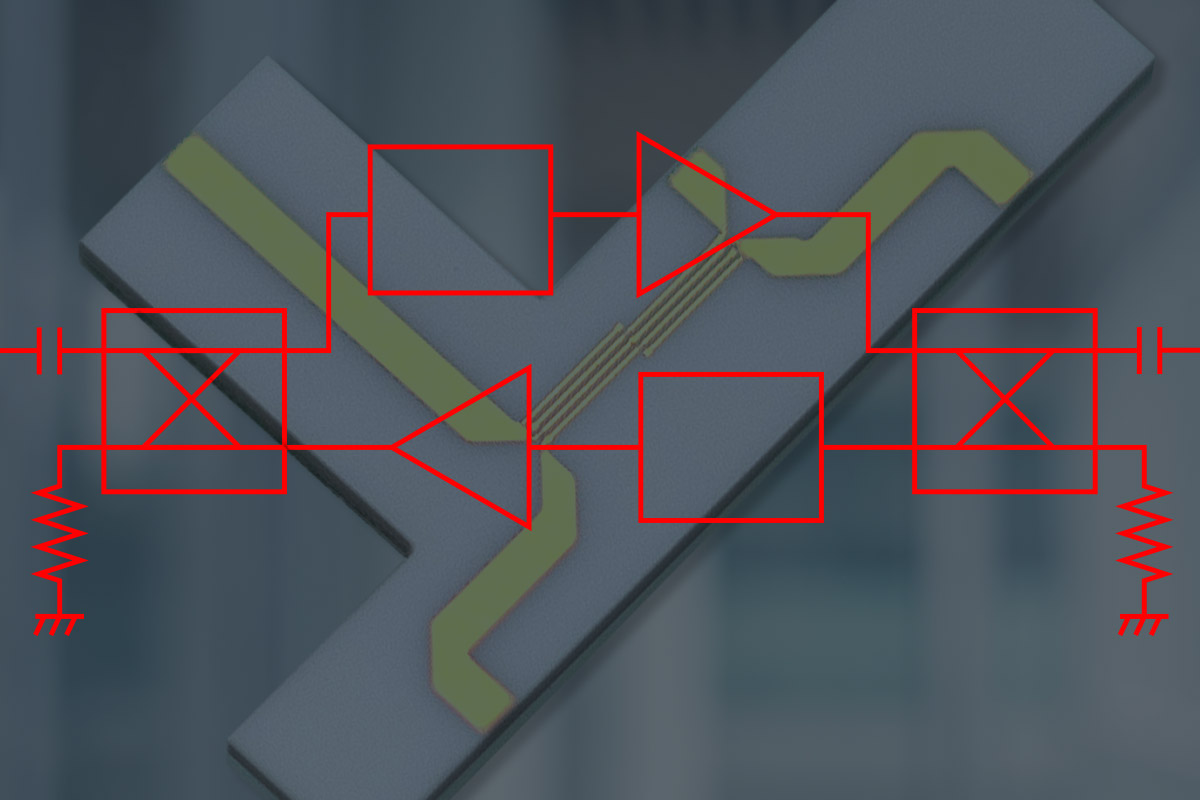
Lange Couplers and Their Use in RF/Microwave System Design

The Lange Coupler was developed by Dr. Julius Lange of Texas Instruments in 1969, while his group was engineering microwave amplifiers on thin film ceramic substrates. The team employed a Bell Labs approach that used 3 dB quadrature couplers, but initially struggled to find the ideal combination of low loss and wide bandwidth. Coupled line connectors could not achieve coupling factors of 3 or 6 dB, as they were too loose. Conversely, the transistors between the interdigitated base and emitter fingers were packed too tightly. Through necessity, invention arose: Lange recalled that geometric symmetry could guarantee the 90° split between outputs known as quadrature. By only moving a portion of the crossovers to the middle, he achieved the desired loss and bandwidth targets.
The Lange Coupler uses four parallel lines, tightly coupled, with alternating lines connected. This method simplified both the construction of the coupler and the numeric effort required to find the equivalent capacitance. It is considered a quadrature hybrid, with 900v measured at each of its two out-of-phase output ports. The construction is somewhat elaborate, in that it uses bonding wires across the lines to maintain the tight coupling critical to optimal performance.
The four ports are shown in Figure 1 below, and the following variables are used to design the coupler:
1) Conductor length (L)
2) Conductor width (W)
3) Conductor spacing (S)
4) Width at port (W1)
5) Bridge width (W2)

Figure 1: Lange Coupler diagram
RF AND MICROWAVE SYSTEM DESIGN CONSIDERATIONS
The construction and port orientation of the Lange Coupler makes it ideal as both a power combiner and splitter for RF and microwave applications. It is a specific type of directional coupler, which allows passive coupling of a defined amount of electromagnetic power. The sweet spot for Lange Couplers has traditionally been UHF to Q-band; the limit becomes frequency. Substrate height and strip width are inversely related to frequency, increasing loss due to the reduced amount of metal available to act as a conductor. As a result, the frequency is a critical system design consideration when selecting coupler types. Figure 2 below shows an example schematic in which Lange Couplers would fit.

Figure 2: Broadband bidirectional amplifier circuit. The quadrature hybrid could implement a Lange Coupler
LANGE COUPLERS’ ROLE IN SYSTEM DESIGN
With an understanding of where they would fit into an RF/microwave circuit along with their limitations, it is possible to define the dB and frequency ranges in which Lange Couplers provide the biggest performance advantages, in terms of low loss, compact layout and wide bandwidth:
• Low loss: < 0.4 dB on 10 GHz frequencies
• Compact layout: as low as 10µm lines and spacing
• Wide bandwidth: 10-50 GHz
CONCLUSIONS AND TAKEAWAYS
Lange Couplers, a specific orientation of directional couplers, are used as passive power combiners and RF/microwave splitters, for a large (but not infinite) range of frequencies. The best-performing designs employ minimized line distance and spacing, along with very tight tolerance control to maximize their advantage.
Learn more about SemiGen's Lange Couplers and contact our technical support team with any questions.


